CA
™
9
The Crest Audio CA9 professional power amplier is designed to achieve unsurpassed sonic performance and long-term reli-
ability— even when operating under extreme stress—in touring or xed installation applications. Absolute sonic accuracy is the
hallmark of every Crest amplier. Bass is solid and dened to the limits of audibility, with ample current reserves delivered by
an “over-engineered” power supply and advanced Class H circuitry. Wide-bandwidth output devices assure detailed, transparent
high frequency response. And, thanks to Crest’s exclusive IGM circuit, the CA9 will drive 2 ohm loads safely without compro-
mise in performance.
Construction and Quality Control
The CA9 is built exclusively in Crest’s own USA manufacturing facility, with internal components selected for premium quality
and proven durability. Each modular subassembly is pre-tested, and the assembled CA9 receives a rigorous “hot room” burn-in
before thorough nal checkout on precision test equipment.
CA 9 Features
• Crest’s legendary “overbuilt” power supply
• Toroidal power transformer
• Latest generation of high-speed, wide-bandwidth output devices
• Twin tunnel cooling with back-to-front air ow
• Dual, variable speed DC fans
• Massive, extruded aluminum heat sinks
• Balanced XLR and 1/4-inch (TRS) inputs
• 5-Way binding post outputs or Speakon™ connectors (market dependent)
• Stereo/parallel/bridged mono mode selector switch
• Ground lift switch
• TourClass® protection circuits
• Recessed, stepped attenuators
• Front panel circuit breaker switch
• Modular construction
Crest Audio Inc.
100 Eisenhower Dr., Paramus NJ 07652 USA
TEL: 201.909.8700 FAX: 201.909.8744
http://www.crestaudio.com
Power figures are watts per chan-
nel, both channels driven.
* 3-Year Warranty with 2 addi-
tional years if Registration Card
is sent to Crest Audio. (USA,
Canada, United Kingdom, and
many other countries).
Crest Audio reserves the right to
make improvements in manufac-
turing or design which may affect
specification.
Crest Audio specification litera-
ture is available in downloadable
PDF format; visit our website at:
http://www.crestaudio.com.
©1997 Crest Audio Inc.
v. 2.6 11/25/97 B5000015
CA2 POWER AMPLIFIER
SPECIFICATIONS
RISK OF ELECTRIC SHOCK
DO NOT OPEN
AVIS : RISQUE DE CHOC ÉLECTRIQUE—NE PAS OUVRIR
WARNING TO REDUCE THE RISK OF FIRE OR ELECTRIC SHOCK DO NOT
EXPOSE THIS EQUIPMENT TO RAIN OR MOISTURE.
ATTENTION! POUR ÉVITER LE RISQUE D'INCENDIE OU DE CHOC
ÉLECTRIQUE, NE PLACEZ PAS CET APPAREIL SOUS LA PLUIE OU Á
L'HUMIDITÉ
CAUTION
A
A
B
AB
A
Designed & manufactured in the USA by:
Crest Audio Inc.
100 Eisenhower Dr.
Paramus, New Jersey 07652 USA
1
3-
2+
+
A
A
B
B
••
•
•
+
+
+
A
B
B
A
A
B
Designed & manufactured in the USA by:
Crest Audio Inc.
100 Eisenhower Dr.
Paramus, New Jersey 07652 USA
A
A
B
AB
A
1
3-
2+
+
•
•
•
•
B
A
NL4FC
B
A
A
B
643-105
A
A
B
B
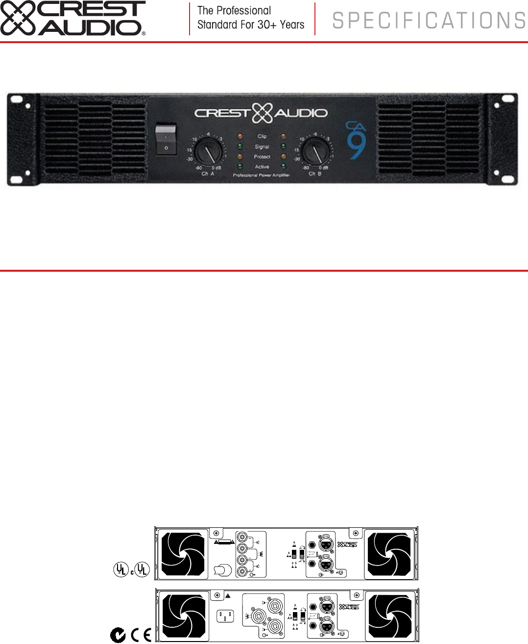
Rear View,
Binding Post
Version
Rear View,
Speakon
Version
(not available in
North America)
1kHz, 0.01% THD+N 20Hz-20kHz, 0.1% THD+N
160W 150W
250W 200W
500W 450W
44V
62V
20Hz-20kHz, -3dB@135kHz
20Hz-20kHz, -.9dB/+.15dB
ACL, IGM, AutoRamp, short circuit, DC voltage,
turn-on/off transient, current inrush, sub/ultrasonic input.
<0.01%
<0.01%
368:1
> - 60dB
0.775V standard (see table below)
X45 standard (see table below)
>20kΩ/>10kΩ
-105dB
> - 60dB
AB
Female XLR (pin 2+, dealer config. for pin 3+), TRS (tip+)
5-way output binding posts or Speakon connectors
(market dependent)
20,000 µF
100V-240V, 50-60Hz
1.2A
3.25A
5.5A
9.0A
1119 BTU/hr
1607 BTU/hr
Back-to-front via 2 rear panel mounted variable-speed DC fans
(filters removable without tools)
Front Panel: 2 attenuators
Rear Panel: signal ground lift switch, mode select switch
Clip/Limit, Signal, Temp/DC, Active
Steel chassis, 16 gauge. Double thickness in rack ear areas.
3.5" x 19" x 18" / 89 x 483 x 457mm
38 lbs. / 17.25 kg., 33 lbs. / 14.98 kg.
5 years
*
8Ω Stereo Power
4Ω Stereo Power
8Ω Bridged Mono Power
Max RMS Output Voltage
(each channel)
Peak Output Voltage (each channel)
Frequency Response (+0 / -0.3dB, 1W/8Ω)
Power Bandwidth (rated power at 4Ω, 1% THD+N)
TourClass
®
Protection
THD+N
(rated power at 4Ω, 1kHz)
SMPTE IMD (rated power at 8Ω, 60Hz & 7kHz)
Damping Factor (10-400Hz at 8Ω)
Input CMRR (1kHz)
Input Sensitivity (rated power at 8Ω )
Voltage Gain
Input Impedance (balanced/unbalanced)
Hum and Noise
(“A” weighted, full power, 4Ω)
Crosstalk (“A” weighted, full power, 4Ω)
Class
Input Connectors
(per channel)
Output Connectors (per channel)
Filter Storage
Power Supply
(factory configured)
Idle Current Draw 120V
1/8 Power Curr. Draw
(typical music, 120V/4Ω)
1/3 Power Curr. Draw (continuous music, 120V/4Ω)
Max Curr. Draw (circuit breaker rating, 120V/4Ω)
Thermal Emissions (1/8 Power, 4Ω)
Thermal Emissions (1/3 Power, 4Ω)
Cooling
Controls
LED Indicators
(per channel)
Construction
Dimensions
(Height x Width x Depth)
Gross Weight, Net Weight
Warranty
Gain Sens
Dealer-Configurable Gain/Sensitivity Options Factory Standard X45 .775V
Option 1 X40 .866V
Option 2 X20 1.73V
*B5000015*
Architect’s & Engineer’s Specifications
The power amplifier shall have two channels. At 8 ohms, 20Hz
- 20kHz, 0.1% THD, it shall deliver a minimum of 150 watts
per channel. At 4 ohms, 20Hz - 20kHz, 0.1% THD, it shall
deliver a minimum of 200 watts per channel. In bridged mono
mode with an 8 ohm load, 20Hz - 20kHz, 0.1% THD, it shall
deliver a minimum of 450 watts.
The amplifier shall have circuitry to protect itself from output
short circuits, thermal overload or other adverse load condi-
tions. The amplifier shall protect speaker loads from DC volt-
age on outputs. The amplifier shall have active clip limiting
and impedance sensing circuitry. Output relays shall protect
the speakers from amplifier failure.
Two rear panel mounted variable speed DC fans (filters
detachable without tools) shall provide back to front air flow
through the chassis.
Each channel shall have a standard (factory-set) input sensitiv-
ity of 0.775 Volts, and shall be fitted with an internal jumper
which allows the gain to be altered to X20 or X40. The hum
and noise level shall be 105 dB below rated output, “A”
weighted. SMPTE IMD shall be less than 0.01% at rated
power, 60Hz and 7kHz. The amplifier shall have a class AB
output stage. The frequency response shall be 20Hz-20kHz,
+0, -0.3dB (1W/8Ω).
The amplifier will operate at 100V-240V, 50-60 Hz AC (config-
ured at factory). Maximum current draw shall not exceed 9
amperes at 120VAC (limited by front panel breaker for bench
tests).
Front panel indicators shall include Active, Protect, Signal,
and Clip LED’s for each channel. Front panel attenuators
shall be recessed and detented.
Rear panel input connectors shall be female TRS and XLR
type, internally dealer-configurable for pin 2 (factory setting)
or pin 3 positive. Output terminations shall be 5-way output
binding posts or Speakon output connectors (market depen-
dent). A ground lift switch and a Stereo/Parallel/Bridged Mono
mode operation switch shall be provided.
A rear-panel IEC AC mains socket (with power cord) or single
AC mains cord having an appropriate AC plug for the intended
operating voltage shall be provided (market dependent).
The packaging of the amplifier shall allow for standard rack
mounting without requiring space between similar units.
Optional rack mount handles will be available. Dimensions
shall be 19" (483mm) wide, 3.5" (89mm) high and 18"
(457mm) deep. The amplifier shall weigh 33 lbs. (14.98 kg)
net, and shall be designated the Crest Audio model CA2.
Crest Audio Inc.
100 Eisenhower Dr., Paramus NJ 07652 USA
TEL: 201.909.8700 FAX: 201.909.8744
http://www.crestaudio.com
Power figures are watts per chan-
nel, both channels driven.
* 3-Year Warranty with 2 addi-
tional years if Registration Card
is sent to Crest Audio. (USA,
Canada, United Kingdom, and
many other countries).
Crest Audio reserves the right to
make improvements in manufac-
turing or design which may affect
specification.
Crest Audio specification litera-
ture is available in downloadable
PDF format; visit our website at:
http://www.crestaudio.com.
©1997 Crest Audio Inc.
v. 2.6 11/25/97 B5000015
CA2 POWER AMPLIFIER
SPECIFICATIONS
RISK OF ELECTRIC SHOCK
DO NOT OPEN
AVIS : RISQUE DE CHOC ÉLECTRIQUE—NE PAS OUVRIR
WARNING TO REDUCE THE RISK OF FIRE OR ELECTRIC SHOCK DO NOT
EXPOSE THIS EQUIPMENT TO RAIN OR MOISTURE.
ATTENTION! POUR ÉVITER LE RISQUE D'INCENDIE OU DE CHOC
ÉLECTRIQUE, NE PLACEZ PAS CET APPAREIL SOUS LA PLUIE OU Á
L'HUMIDITÉ
CAUTION
A
A
B
AB
A
Designed & manufactured in the USA by:
Crest Audio Inc.
100 Eisenhower Dr.
Paramus, New Jersey 07652 USA
1
3-
2+
+
A
A
B
B
••
•
•
+
+
+
A
B
B
A
A
B
Designed & manufactured in the USA by:
Crest Audio Inc.
100 Eisenhower Dr.
Paramus, New Jersey 07652 USA
A
A
B
AB
A
1
3-
2+
+
•
•
•
•
B
A
NL4FC
B
A
A
B
643-105
A
A
B
B
Rear View,
Binding Post
Version
Rear View,
Speakon
Version
(not available in
North America)
1kHz, 0.01% THD+N 20Hz-20kHz, 0.1% THD+N
160W 150W
250W 200W
500W 450W
44V
62V
20Hz-20kHz, -3dB@135kHz
20Hz-20kHz, -.9dB/+.15dB
ACL, IGM, AutoRamp, short circuit, DC voltage,
turn-on/off transient, current inrush, sub/ultrasonic input.
<0.01%
<0.01%
368:1
> - 60dB
0.775V standard (see table below)
X45 standard (see table below)
>20kΩ/>10kΩ
-105dB
> - 60dB
AB
Female XLR (pin 2+, dealer config. for pin 3+), TRS (tip+)
5-way output binding posts or Speakon connectors
(market dependent)
20,000 µF
100V-240V, 50-60Hz
1.2A
3.25A
5.5A
9.0A
1119 BTU/hr
1607 BTU/hr
Back-to-front via 2 rear panel mounted variable-speed DC fans
(filters removable without tools)
Front Panel: 2 attenuators
Rear Panel: signal ground lift switch, mode select switch
Clip/Limit, Signal, Temp/DC, Active
Steel chassis, 16 gauge. Double thickness in rack ear areas.
3.5" x 19" x 18" / 89 x 483 x 457mm
38 lbs. / 17.25 kg., 33 lbs. / 14.98 kg.
5 years
*
8Ω Stereo Power
4Ω Stereo Power
8Ω Bridged Mono Power
Max RMS Output Voltage
(each channel)
Peak Output Voltage (each channel)
Frequency Response (+0 / -0.3dB, 1W/8Ω)
Power Bandwidth (rated power at 4Ω, 1% THD+N)
TourClass
®
Protection
THD+N
(rated power at 4Ω, 1kHz)
SMPTE IMD (rated power at 8Ω, 60Hz & 7kHz)
Damping Factor (10-400Hz at 8Ω)
Input CMRR (1kHz)
Input Sensitivity (rated power at 8Ω )
Voltage Gain
Input Impedance (balanced/unbalanced)
Hum and Noise
(“A” weighted, full power, 4Ω)
Crosstalk (“A” weighted, full power, 4Ω)
Class
Input Connectors
(per channel)
Output Connectors (per channel)
Filter Storage
Power Supply
(factory configured)
Idle Current Draw 120V
1/8 Power Curr. Draw
(typical music, 120V/4Ω)
1/3 Power Curr. Draw (continuous music, 120V/4Ω)
Max Curr. Draw (circuit breaker rating, 120V/4Ω)
Thermal Emissions (1/8 Power, 4Ω)
Thermal Emissions (1/3 Power, 4Ω)
Cooling
Controls
LED Indicators
(per channel)
Construction
Dimensions
(Height x Width x Depth)
Gross Weight, Net Weight
Warranty
Gain Sens
Dealer-Configurable Gain/Sensitivity Options Factory Standard X45 .775V
Option 1 X40 .866V
Option 2 X20 1.73V
*B5000015*
Architect’s & Engineer’s Specifications
The power amplifier shall have two channels. At 8 ohms, 20Hz
- 20kHz, 0.1% THD, it shall deliver a minimum of 150 watts
per channel. At 4 ohms, 20Hz - 20kHz, 0.1% THD, it shall
deliver a minimum of 200 watts per channel. In bridged mono
mode with an 8 ohm load, 20Hz - 20kHz, 0.1% THD, it shall
deliver a minimum of 450 watts.
The amplifier shall have circuitry to protect itself from output
short circuits, thermal overload or other adverse load condi-
tions. The amplifier shall protect speaker loads from DC volt-
age on outputs. The amplifier shall have active clip limiting
and impedance sensing circuitry. Output relays shall protect
the speakers from amplifier failure.
Two rear panel mounted variable speed DC fans (filters
detachable without tools) shall provide back to front air flow
through the chassis.
Each channel shall have a standard (factory-set) input sensitiv-
ity of 0.775 Volts, and shall be fitted with an internal jumper
which allows the gain to be altered to X20 or X40. The hum
and noise level shall be 105 dB below rated output, “A”
weighted. SMPTE IMD shall be less than 0.01% at rated
power, 60Hz and 7kHz. The amplifier shall have a class AB
output stage. The frequency response shall be 20Hz-20kHz,
+0, -0.3dB (1W/8Ω).
The amplifier will operate at 100V-240V, 50-60 Hz AC (config-
ured at factory). Maximum current draw shall not exceed 9
amperes at 120VAC (limited by front panel breaker for bench
tests).
Front panel indicators shall include Active, Protect, Signal,
and Clip LED’s for each channel. Front panel attenuators
shall be recessed and detented.
Rear panel input connectors shall be female TRS and XLR
type, internally dealer-configurable for pin 2 (factory setting)
or pin 3 positive. Output terminations shall be 5-way output
binding posts or Speakon output connectors (market depen-
dent). A ground lift switch and a Stereo/Parallel/Bridged Mono
mode operation switch shall be provided.
A rear-panel IEC AC mains socket (with power cord) or single
AC mains cord having an appropriate AC plug for the intended
operating voltage shall be provided (market dependent).
The packaging of the amplifier shall allow for standard rack
mounting without requiring space between similar units.
Optional rack mount handles will be available. Dimensions
shall be 19" (483mm) wide, 3.5" (89mm) high and 18"
(457mm) deep. The amplifier shall weigh 33 lbs. (14.98 kg)
net, and shall be designated the Crest Audio model CA2.
www.crestaudio.com
 Manymanuals.com
 Manymanuals.de
 Manymanuals.fr
 Manymanuals.it
 Manymanuals.pl
 Manymanuals.cz
 Manymanuals.es
 Manymanuals-pt.com
Commentaires sur ces manuels